Digital Timer Switch Circuit Diagram . in this tutorial, you'll learn how to use the 555 timer to make useful projects to blink lights, create timing circuits, and make sound. The hardware part of this project is very simple. this simple digital timer circuit can be used to obtain timing output through selectable. Timer meters are employed in. The entire circuit runs off a regulated 5v power supply derived using the popular lm7805. A timer is a control device that outputs a signal at a preset time after an input signal is. this video shows digital timer switch electrical wiring diagram. Learn how to connect a digital timer with a comprehensive connection diagram. digital timer connection refers to the process of connecting a digital timer device to an electrical system or circuit in order to control and automate the timing of various electrical operations.
from www.circuits-diy.com
in this tutorial, you'll learn how to use the 555 timer to make useful projects to blink lights, create timing circuits, and make sound. Learn how to connect a digital timer with a comprehensive connection diagram. The hardware part of this project is very simple. A timer is a control device that outputs a signal at a preset time after an input signal is. digital timer connection refers to the process of connecting a digital timer device to an electrical system or circuit in order to control and automate the timing of various electrical operations. this video shows digital timer switch electrical wiring diagram. The entire circuit runs off a regulated 5v power supply derived using the popular lm7805. this simple digital timer circuit can be used to obtain timing output through selectable. Timer meters are employed in.
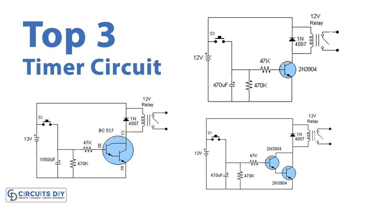
Top 3 Simple Timer Circuits
Digital Timer Switch Circuit Diagram this video shows digital timer switch electrical wiring diagram. Learn how to connect a digital timer with a comprehensive connection diagram. The entire circuit runs off a regulated 5v power supply derived using the popular lm7805. A timer is a control device that outputs a signal at a preset time after an input signal is. The hardware part of this project is very simple. this simple digital timer circuit can be used to obtain timing output through selectable. digital timer connection refers to the process of connecting a digital timer device to an electrical system or circuit in order to control and automate the timing of various electrical operations. Timer meters are employed in. in this tutorial, you'll learn how to use the 555 timer to make useful projects to blink lights, create timing circuits, and make sound. this video shows digital timer switch electrical wiring diagram.
From www.circuits-diy.com
Top 3 Simple Timer Circuits Digital Timer Switch Circuit Diagram digital timer connection refers to the process of connecting a digital timer device to an electrical system or circuit in order to control and automate the timing of various electrical operations. Timer meters are employed in. this simple digital timer circuit can be used to obtain timing output through selectable. Learn how to connect a digital timer with. Digital Timer Switch Circuit Diagram.
From www.youtube.com
How to Make Connect a Digital Timer Wiring Diagram digital timer Digital Timer Switch Circuit Diagram this video shows digital timer switch electrical wiring diagram. Timer meters are employed in. The hardware part of this project is very simple. The entire circuit runs off a regulated 5v power supply derived using the popular lm7805. this simple digital timer circuit can be used to obtain timing output through selectable. in this tutorial, you'll learn. Digital Timer Switch Circuit Diagram.
From enginemanualerik.z19.web.core.windows.net
Digital Timer Wiring Diagram Digital Timer Switch Circuit Diagram this simple digital timer circuit can be used to obtain timing output through selectable. A timer is a control device that outputs a signal at a preset time after an input signal is. The hardware part of this project is very simple. Timer meters are employed in. The entire circuit runs off a regulated 5v power supply derived using. Digital Timer Switch Circuit Diagram.
From wiringengineabt.z19.web.core.windows.net
Delay Timer Switch Circuit Diagram Digital Timer Switch Circuit Diagram The hardware part of this project is very simple. this simple digital timer circuit can be used to obtain timing output through selectable. this video shows digital timer switch electrical wiring diagram. Learn how to connect a digital timer with a comprehensive connection diagram. in this tutorial, you'll learn how to use the 555 timer to make. Digital Timer Switch Circuit Diagram.
From circuitmanualfink.z6.web.core.windows.net
Digital Timer Switch Wiring Diagram Digital Timer Switch Circuit Diagram A timer is a control device that outputs a signal at a preset time after an input signal is. Timer meters are employed in. digital timer connection refers to the process of connecting a digital timer device to an electrical system or circuit in order to control and automate the timing of various electrical operations. in this tutorial,. Digital Timer Switch Circuit Diagram.
From schematron.org
Defiant Digital Timer Wiring Wiring Diagram Pictures Digital Timer Switch Circuit Diagram Timer meters are employed in. The entire circuit runs off a regulated 5v power supply derived using the popular lm7805. this simple digital timer circuit can be used to obtain timing output through selectable. in this tutorial, you'll learn how to use the 555 timer to make useful projects to blink lights, create timing circuits, and make sound.. Digital Timer Switch Circuit Diagram.
From organicled74.blogspot.com
Defiant Digital Timer Wiring Diagram Organicled Digital Timer Switch Circuit Diagram Learn how to connect a digital timer with a comprehensive connection diagram. A timer is a control device that outputs a signal at a preset time after an input signal is. this simple digital timer circuit can be used to obtain timing output through selectable. this video shows digital timer switch electrical wiring diagram. Timer meters are employed. Digital Timer Switch Circuit Diagram.
From enginemanualerik.z19.web.core.windows.net
Digital Timer Circuit Diagram Digital Timer Switch Circuit Diagram Timer meters are employed in. in this tutorial, you'll learn how to use the 555 timer to make useful projects to blink lights, create timing circuits, and make sound. this video shows digital timer switch electrical wiring diagram. this simple digital timer circuit can be used to obtain timing output through selectable. The entire circuit runs off. Digital Timer Switch Circuit Diagram.
From wiringengineabt.z19.web.core.windows.net
Digital Circuits Diagram Digital Timer Switch Circuit Diagram The entire circuit runs off a regulated 5v power supply derived using the popular lm7805. The hardware part of this project is very simple. A timer is a control device that outputs a signal at a preset time after an input signal is. Learn how to connect a digital timer with a comprehensive connection diagram. Timer meters are employed in.. Digital Timer Switch Circuit Diagram.
From www.youtube.com
How To Make Digital Timer Operation Wiring Diagram timer switch YouTube Digital Timer Switch Circuit Diagram The entire circuit runs off a regulated 5v power supply derived using the popular lm7805. A timer is a control device that outputs a signal at a preset time after an input signal is. in this tutorial, you'll learn how to use the 555 timer to make useful projects to blink lights, create timing circuits, and make sound. . Digital Timer Switch Circuit Diagram.
From www.electricaltechnology.org
1 to 15 Minute Timer Circuit Diagram, Working and Applications Digital Timer Switch Circuit Diagram this video shows digital timer switch electrical wiring diagram. The entire circuit runs off a regulated 5v power supply derived using the popular lm7805. this simple digital timer circuit can be used to obtain timing output through selectable. digital timer connection refers to the process of connecting a digital timer device to an electrical system or circuit. Digital Timer Switch Circuit Diagram.
From guidelibkilometers.z22.web.core.windows.net
Programmable Digital Timer Circuit Digital Timer Switch Circuit Diagram digital timer connection refers to the process of connecting a digital timer device to an electrical system or circuit in order to control and automate the timing of various electrical operations. A timer is a control device that outputs a signal at a preset time after an input signal is. in this tutorial, you'll learn how to use. Digital Timer Switch Circuit Diagram.
From www.youtube.com
3 Phase Contactor Wiring Diagram with Digital Timer Timer Switch Digital Timer Switch Circuit Diagram this simple digital timer circuit can be used to obtain timing output through selectable. The entire circuit runs off a regulated 5v power supply derived using the popular lm7805. this video shows digital timer switch electrical wiring diagram. The hardware part of this project is very simple. A timer is a control device that outputs a signal at. Digital Timer Switch Circuit Diagram.
From userdatascratching.z22.web.core.windows.net
Digital Timer Switch Circuit Diagram Digital Timer Switch Circuit Diagram this video shows digital timer switch electrical wiring diagram. Timer meters are employed in. A timer is a control device that outputs a signal at a preset time after an input signal is. Learn how to connect a digital timer with a comprehensive connection diagram. in this tutorial, you'll learn how to use the 555 timer to make. Digital Timer Switch Circuit Diagram.
From www.chanish.org
3 Phase Timer Switch Circuit Digital Timer Switch Circuit Diagram this video shows digital timer switch electrical wiring diagram. digital timer connection refers to the process of connecting a digital timer device to an electrical system or circuit in order to control and automate the timing of various electrical operations. The hardware part of this project is very simple. this simple digital timer circuit can be used. Digital Timer Switch Circuit Diagram.
From philipworther1969.blogspot.com
Digital Timer Switch Wiring Diagram Digital Timer Switch Circuit Diagram Timer meters are employed in. this simple digital timer circuit can be used to obtain timing output through selectable. The entire circuit runs off a regulated 5v power supply derived using the popular lm7805. The hardware part of this project is very simple. Learn how to connect a digital timer with a comprehensive connection diagram. digital timer connection. Digital Timer Switch Circuit Diagram.
From circuitteqandiner.z13.web.core.windows.net
Digital Clock Circuit Diagram Using 555 Timer Digital Timer Switch Circuit Diagram Learn how to connect a digital timer with a comprehensive connection diagram. The entire circuit runs off a regulated 5v power supply derived using the popular lm7805. A timer is a control device that outputs a signal at a preset time after an input signal is. The hardware part of this project is very simple. Timer meters are employed in.. Digital Timer Switch Circuit Diagram.
From easywiring.info
Timer Switch Diagram Easy Wiring Digital Timer Switch Circuit Diagram The hardware part of this project is very simple. digital timer connection refers to the process of connecting a digital timer device to an electrical system or circuit in order to control and automate the timing of various electrical operations. Timer meters are employed in. A timer is a control device that outputs a signal at a preset time. Digital Timer Switch Circuit Diagram.